
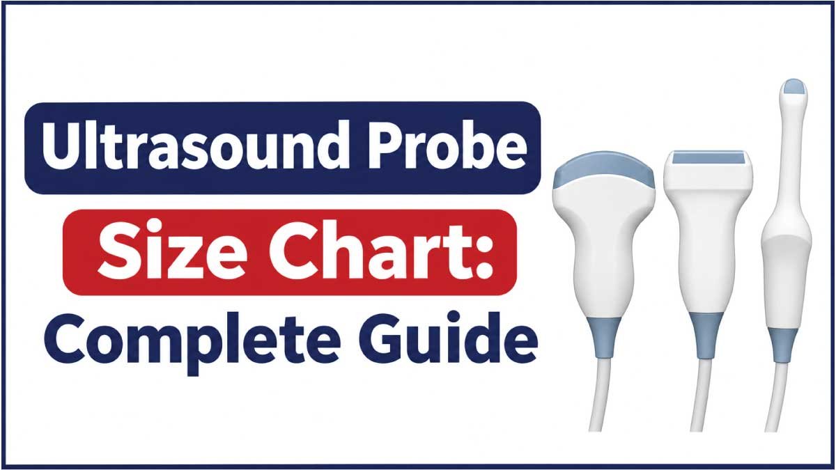
Choosing the correct ultrasound probe is essential for obtaining clear diagnostic images and performing examinations effectively. Ultrasound probes, also called transducers, are available in different shapes, sizes, frequencies, and configurations. Each type is designed for particular imaging applications, such as abdominal examinations, cardiac imaging, vascular studies, and musculoskeletal assessments.
An ultrasound probe size chart helps healthcare professionals, medical equipment buyers, technicians, and students compare probe dimensions, footprints, frequency ranges, and common applications. Understanding these measurements also makes it easier to identify compatible transducers and select suitable equipment for different clinical environments.
This guide covers common ultrasound probe types, their typical dimensions, manufacturer-specific examples, footprint measurements, frequency ranges, and practical selection considerations. It also explains how to measure an ultrasound probe and interpret its technical specifications accurately.
1. What Is an Ultrasound Probe?
An ultrasound probe is a handheld medical device that transmits high-frequency sound waves into the body and receives the returning echoes. The ultrasound machine processes these echoes to create images of internal organs, tissues, blood vessels, and other anatomical structures.
An ultrasound probe is also known as an ultrasound transducer. Both terms generally describe the same imaging component.
A typical ultrasound probe consists of several parts:
- Transducer head: The part that contacts the patient’s skin or is used for specialized internal examinations.
- Acoustic lens: Helps direct and focus ultrasound waves.
- Piezoelectric elements: Convert electrical energy into sound waves and returning echoes into electrical signals.
- Probe housing: Protects the internal components.
- Cable: Connects the probe to the ultrasound machine.
- Connector: Attaches the transducer to a compatible ultrasound system.
The physical dimensions of a probe depend on its imaging technology, intended application, frequency range, and manufacturer.
Some probes have wide, flat scanning surfaces, while others have compact curved or sector-shaped footprints.
2. Ultrasound Probe Size Chart
Ultrasound probes are available in several configurations, and their dimensions vary between manufacturers and models.
The following chart provides approximate footprint categories for common transducer types. These ranges are general comparison guidelines, not universal standardized dimensions.
| Ultrasound Probe Type | Approx. Footprint Width | Approx. Footprint Length | Common Frequency Range |
|---|---|---|---|
| Linear probe | 10–20 mm | 35–60 mm | 5–18 MHz |
| Convex probe | 15–25 mm | 50–75 mm | 2–6 MHz |
| Micro-convex probe | 10–20 mm | 15–30 mm | 3–10 MHz |
| Phased array probe | 15–25 mm | 15–30 mm | 1–5 MHz |
| Endocavitary probe | 12–25 mm | 15–30 mm (scanning face) | 4–10 MHz |
| Transesophageal probe | Model-specific | Model-specific | 3–8 MHz |
| 3D/4D volume probe | 25–40 mm | 45–70 mm | 2–9 MHz |
Important: These are approximate planning ranges intended to explain differences between probe categories. Actual footprints and frequency ranges can fall outside these values. Always check the technical datasheet for the exact model.
Understanding Ultrasound Probe Measurements
Several measurements are used when describing ultrasound transducers.
- Footprint width: The width of the probe’s scanning contact surface.
- Footprint length: The length of the scanning surface or its specified physical dimension.
- Probe length: The overall physical length of the transducer, which may include its handle.
- Probe width: The widest measurement across the probe housing.
- Convex radius: The radius of curvature of a curved transducer surface.
- Frequency: The operating frequency range, measured in megahertz (MHz).
Footprint measurements are particularly important because they describe the portion of the probe that interacts with the scanning area.
3. Different Types of Ultrasound Probes and Their Sizes
Each ultrasound probe type has a different physical design and imaging purpose. Understanding these differences helps healthcare professionals select appropriate equipment.
Linear Ultrasound Probe
A linear ultrasound probe has a flat, rectangular scanning surface. Its transducer elements are arranged in a straight line, producing rectangular images.
Linear probes generally operate at higher frequencies than conventional abdominal probes.
Typical characteristics:
- Approximate footprint length: 35–60 mm.
- Approximate footprint width: 10–20 mm.
- Common frequency range: 5–18 MHz.
- Flat scanning surface.
- High-resolution imaging of superficial structures.
Common applications:
- Blood vessel examinations.
- Thyroid imaging.
- Breast examinations.
- Musculoskeletal imaging.
- Tendon and ligament assessments.
- Vascular access procedures.
- Superficial soft tissue examinations.
Linear probes are particularly useful when detailed imaging of structures close to the skin is required.
Convex Ultrasound Probe
A convex ultrasound probe, also called a curvilinear probe, has a curved scanning surface. Its design produces a wider field of view that expands with increasing imaging depth.
These probes commonly operate at lower frequencies than linear transducers.
Typical characteristics:
- Approximate footprint length: 50–75 mm.
- Approximate footprint width: 15–25 mm.
- Common frequency range: 2–6 MHz.
- Curved scanning surface.
- Suitable for deeper anatomical structures.
Common applications:
- Abdominal examinations.
- Obstetric imaging.
- Pelvic examinations.
- Kidney and bladder imaging.
- General abdominal assessments.
The larger curved footprint helps provide a broad scanning field for examining deeper structures.
Micro-Convex Ultrasound Probe
A micro-convex probe is a smaller version of a conventional convex transducer. It has a compact curved scanning surface and is designed for applications where a smaller footprint is beneficial.
Typical characteristics:
- Approximate footprint length: 15–30 mm.
- Approximate footprint width: 10–20 mm.
- Common frequency range: 3–10 MHz.
- Small curved scanning surface.
- Compact design.
Common applications:
- Pediatric examinations.
- Neonatal imaging.
- Intercostal scanning.
- Small anatomical areas.
- Specialized abdominal examinations.
Micro-convex probes are useful when conventional convex transducers are too large for the available scanning window.
Phased Array Ultrasound Probe
A phased array probe has a relatively small contact surface and uses electronically controlled beam steering to create sector-shaped images.
Its compact footprint makes it useful for imaging through narrow acoustic windows.
Typical characteristics:
- Approximate footprint width: 15–25 mm.
- Approximate footprint length: 15–30 mm.
- Common frequency range: 1–5 MHz.
- Small scanning surface.
- Sector-shaped imaging field.
Common applications:
- Cardiac examinations.
- Echocardiography.
- Intercostal imaging.
- Thoracic examinations.
- Selected abdominal examinations.
The small footprint allows the probe to fit between the ribs during many cardiac imaging examinations.
Endocavitary Ultrasound Probe
Endocavitary probes are designed for internal examinations. They generally have an elongated housing with a compact curved or specialized scanning head.
Two common applications are transvaginal and transrectal imaging.
Typical characteristics:
- Compact scanning head.
- Elongated probe housing.
- Curved or sector-shaped imaging surface.
- Common frequency range: 4–10 MHz.
- Specialized internal examination design.
Common applications:
- Transvaginal ultrasound.
- Transrectal ultrasound.
- Prostate examinations.
- Pelvic imaging.
- Early pregnancy examinations.
Because these probes are used internally, compatibility, cleaning, disinfection, and protective cover requirements must be considered.
Transesophageal Echocardiography Probe
A transesophageal echocardiography (TEE) probe is designed for cardiac imaging from inside the esophagus.
It typically contains a small ultrasound transducer mounted at the end of a flexible insertion assembly.
Important characteristics:
- Specialized insertion tube.
- Small imaging head.
- Steering and positioning mechanisms.
- Model-specific shaft and insertion dimensions.
- Specialized cardiac imaging technology.
TEE probes are not directly comparable to conventional external ultrasound probes because their physical design and clinical use are different.
3D and 4D Ultrasound Probes
Three-dimensional and four-dimensional ultrasound probes capture volume information rather than producing only conventional two-dimensional images.
Depending on their design, they may use mechanical scanning mechanisms or matrix-array technology.
Common applications:
- Obstetric imaging.
- Fetal examinations.
- Gynecological imaging.
- Selected cardiac examinations.
Their physical footprints vary considerably according to the imaging system and transducer design.
4. Actual Ultrasound Probe Dimensions: Manufacturer Examples
Generic size charts are useful for understanding equipment categories, but manufacturer specifications provide more precise measurements.
The following examples illustrate actual published ultrasound transducer footprints from GE Healthcare equipment documentation.
GE Healthcare Voluson Transducer Dimensions
The following measurements are taken from published Voluson transducer specifications.
| Probe Model | Probe Type | Footprint (mm) | Frequency Range |
|---|---|---|---|
| 4C-RS | Convex | 68.7 × 18.3 | 2–5 MHz |
| E8C-RS | Micro-convex endocavitary | 22.1 × 10.7 | 4–10 MHz |
| 12L-RS | Linear | 47.2 × 13.8 | 4–12 MHz |
| 3Sc-RS | Phased array | 23.7 × 18.4 | 1–4 MHz |
| RAB2-6-RS | 3D/4D convex | 62.2 × 34.0 | 2–5 MHz |
| RIC5-9W-RS | 3D/4D endocavitary | 22.4 × 22.6 | 4–9 MHz |
These examples demonstrate that different probe designs have considerably different scanning footprints.
For instance, the 4C-RS convex transducer has a much longer footprint than the 3Sc-RS phased array transducer.
Additional GE Healthcare Probe Examples
Another published GE transducer guide provides the following specifications:
| Probe Model | Probe Type | Footprint (mm) | Frequency Range |
|---|---|---|---|
| 9L-RS | Linear | 49.3 × 9.2 | 3.33–10 MHz |
| 3Sc-RS | Phased array | 27.6 × 19.3 | 1.7–4 MHz |
| 6S-RS | Phased array | 23.5 × 16.8 | 2.5–7 MHz |
| C1-5-RS | Convex | 66.2 × 18.3 | 2–5 MHz |
| 8C-RS | Micro-convex | 22 × 12 | 4–10 MHz |
These measurements belong to specific transducer models and should not be treated as universal dimensions for all linear, convex, or phased array probes.
5. Ultrasound Probe Frequency Chart
Frequency is one of the most important specifications when comparing ultrasound transducers.
It is measured in megahertz (MHz) and describes the number of sound-wave cycles produced per second.
The operating frequency affects image resolution and penetration depth.
| Frequency Range | General Imaging Characteristics | Common Applications |
|---|---|---|
| 1–3 MHz | Greater penetration, lower resolution | Deep abdominal and cardiac imaging |
| 2–5 MHz | Deep tissue imaging | Abdomen and obstetrics |
| 3–7 MHz | Intermediate penetration | General abdominal and pediatric imaging |
| 5–10 MHz | Higher detail for relatively superficial structures | Vascular and small parts |
| 8–15 MHz | High-resolution superficial imaging | Thyroid, breast and musculoskeletal |
| 15–22 MHz | Very high-resolution superficial imaging | Specialized superficial imaging |
These are general frequency categories rather than fixed probe classifications. Actual operating frequencies depend on the transducer and selected imaging mode.
High-Frequency Ultrasound Probes
High-frequency probes generally provide better spatial resolution for superficial structures but have less penetration than lower-frequency probes.
They are commonly used for:
- Small blood vessels.
- Tendons and ligaments.
- Thyroid examinations.
- Superficial masses.
- Skin and soft tissue imaging.
Low-Frequency Ultrasound Probes
Low-frequency probes are generally more suitable for imaging deeper anatomical structures.
Common applications include:
- Abdominal examinations.
- Deep pelvic imaging.
- Cardiac imaging.
- Selected obstetric examinations.
The appropriate frequency depends on the patient’s anatomy, examination requirements, and imaging conditions.
Also Read:
6. Ultrasound Probe Footprint Size Chart
The footprint is the physical contact area of an ultrasound probe. It is particularly important when selecting transducers for examinations involving limited access or narrow anatomical spaces.
The following table summarizes representative manufacturer-specific footprint examples.
| Probe Type | Example Footprint | Measurement Unit |
|---|---|---|
| Linear | 47.2 × 13.8 | mm |
| Linear | 49.3 × 9.2 | mm |
| Convex | 68.7 × 18.3 | mm |
| Convex | 66.2 × 18.3 | mm |
| Micro-convex | 22.0 × 12.0 | mm |
| Endocavitary | 22.1 × 10.7 | mm |
| Phased array | 23.7 × 18.4 | mm |
| 3D/4D convex | 62.2 × 34.0 | mm |
Why Footprint Size Matters
Footprint size influences how the probe contacts the body and accesses different anatomical regions.
A smaller footprint can be advantageous when:
- Scanning between the ribs.
- Examining small anatomical structures.
- Working in restricted spaces.
- Performing pediatric examinations.
- Accessing specific internal scanning locations.
A larger footprint can provide a broader contact surface and may be useful for conventional abdominal examinations.
However, footprint size alone does not determine imaging performance. Frequency, array technology, beam characteristics, and transducer design are also important.
Also Read:
7. Ultrasound Probe Size Conversion Chart
Medical equipment specifications may be listed in millimeters, centimeters, or inches.
Understanding these units helps when comparing probes from different manufacturers.
| Millimeters (mm) | Centimeters (cm) | Inches (in) |
|---|---|---|
| 5 mm | 0.5 cm | 0.20 in |
| 10 mm | 1 cm | 0.39 in |
| 15 mm | 1.5 cm | 0.59 in |
| 20 mm | 2 cm | 0.79 in |
| 25 mm | 2.5 cm | 0.98 in |
| 30 mm | 3 cm | 1.18 in |
| 35 mm | 3.5 cm | 1.38 in |
| 40 mm | 4 cm | 1.57 in |
| 45 mm | 4.5 cm | 1.77 in |
| 50 mm | 5 cm | 1.97 in |
| 60 mm | 6 cm | 2.36 in |
| 70 mm | 7 cm | 2.76 in |
| 80 mm | 8 cm | 3.15 in |
| 100 mm | 10 cm | 3.94 in |
How to Convert Probe Measurements
Use these standard formulas:
Millimeters to centimeters:
Centimeters = Millimeters ÷ 10
Centimeters to millimeters:
Millimeters = Centimeters × 10
Millimeters to inches:
Inches = Millimeters ÷ 25.4
For example, a probe footprint measuring 47.2 mm is equivalent to 4.72 cm or approximately 1.86 inches.
8. How to Measure an Ultrasound Probe
Accurate measurements help identify the correct transducer, compare equipment, and determine whether a probe fits a particular storage or accessory arrangement.
Follow these steps:
Step 1: Identify the Probe Type
Determine whether the transducer is linear, convex, micro-convex, phased array, or endocavitary.
Its shape will help determine which measurements are relevant.
Step 2: Measure the Footprint Width
Measure across the scanning contact surface from one side to the other.
For curved probes, use the manufacturer’s specified measurement rather than assuming that a straight-line measurement represents every aspect of the curved surface.
Step 3: Measure the Footprint Length
Measure the scanning surface along its longest dimension.
Do not confuse the footprint length with the overall length of the probe housing.
Step 4: Measure the Overall Probe Length
If you need the complete physical dimensions, measure from the end of the transducer head to the end of the probe housing.
Record the cable separately.
Step 5: Record the Convex Radius
For curved transducers, check the manufacturer’s stated radius of curvature.
This measurement is commonly expressed in millimeters.
Step 6: Record Frequency and Model Information
Write down the probe model number, frequency range, compatible ultrasound systems, and footprint specifications.
Manufacturer documentation should be used whenever precise technical measurements are required.
9. How to Choose the Correct Ultrasound Probe Size
Selecting the right ultrasound probe requires considering the examination type, anatomical location, imaging depth, and equipment compatibility.
Consider the Examination Application
Different probes are designed for different clinical purposes.
For example:
- Linear probes are commonly selected for vascular and superficial imaging.
- Convex probes are commonly used for abdominal examinations.
- Phased array probes are commonly used for cardiac imaging.
- Micro-convex probes can be useful in pediatric and specialized examinations.
- Endocavitary probes are designed for internal imaging.
The intended clinical application should guide the selection.
Evaluate Imaging Depth
The required penetration depth affects the choice of frequency and probe design.
Deeper structures generally require lower-frequency imaging, while superficial structures often benefit from higher-frequency imaging.
Check Footprint Dimensions
A smaller scanning surface can be useful when access is restricted.
A broader footprint may be appropriate for examinations that require a wider contact surface.
Verify Ultrasound Machine Compatibility
Not every ultrasound probe works with every ultrasound machine.
Before purchasing a replacement transducer, confirm:
- Manufacturer compatibility.
- Supported probe model.
- Connector type.
- Imaging frequency support.
- Software compatibility.
- Supported imaging modes.
A probe that looks physically similar to another model is not necessarily interchangeable.
Consider Cleaning and Storage Requirements
Probe storage and reprocessing requirements depend on the transducer’s intended use.
External probes, endocavitary probes, and specialized internal transducers may require different cleaning and disinfection procedures.
Always follow the manufacturer’s instructions and applicable infection-control requirements.
10. Common Mistakes When Comparing Ultrasound Probe Sizes
Comparing ultrasound transducers requires attention to more than their overall physical dimensions.
Avoid these common mistakes:
- Confusing footprint with total probe length: The scanning surface and complete housing are different measurements.
- Assuming every linear probe has the same dimensions: Footprint sizes vary between models and manufacturers.
- Ignoring frequency range: Two probes with similar footprints may have very different imaging capabilities.
- Confusing convex and micro-convex probes: Their scanning surfaces and intended applications differ.
- Ignoring connector compatibility: Similar-looking probes may not work with the same ultrasound system.
- Using generic size charts as exact specifications: Approximate category ranges should not replace manufacturer documentation.
- Ignoring cleaning requirements: Specialized probes may require specific reprocessing procedures.
Accurate technical specifications are particularly important when ordering replacement probes or planning medical equipment purchases.
11. Frequently Asked Questions About Ultrasound Probe Sizes
1. What is the standard size of an ultrasound probe?
There is no universal standard size. Linear probes, convex probes, phased array probes, and endocavitary probes have different footprints and physical configurations. Exact measurements depend on the manufacturer and model.
2. What is the footprint of an ultrasound probe?
The footprint is the scanning contact surface of the transducer. It is generally measured in millimeters and describes the area that contacts the patient’s body or examination surface.
3. What is the typical size of a linear ultrasound probe?
Linear probe footprints commonly fall within an approximate range of 35–60 mm in length and 10–20 mm in width. Actual dimensions vary by model.
4. Which ultrasound probe has the smallest footprint?
Phased array and micro-convex probes commonly have relatively small footprints. However, exact dimensions depend on the specific transducer design.
5. What is the difference between a convex and linear ultrasound probe?
A linear probe has a flat scanning surface and generally produces rectangular images. A convex probe has a curved scanning surface and produces a wider, fan-shaped image. They are used for different imaging applications.
6. What does MHz mean in an ultrasound probe?
MHz stands for megahertz and measures the frequency of ultrasound waves. Higher frequencies generally provide better detail for superficial structures, while lower frequencies generally provide greater penetration.
7. Are ultrasound probe sizes the same for every manufacturer?
No. GE, Philips, Siemens, Canon, Mindray, and other manufacturers offer transducers with different physical dimensions, frequencies, and connector designs.
8. How is an ultrasound probe footprint measured?
The footprint is measured across the scanning contact surface. Its width and length are recorded separately, following the measurement method specified by the manufacturer.
9. Can I use any ultrasound probe with my ultrasound machine?
No. Probe compatibility depends on the ultrasound system, connector, electronics, supported frequencies, and software configuration. Always verify compatibility before purchasing a transducer.
10. Where can I find exact ultrasound probe dimensions?
The manufacturer’s technical datasheet, transducer guide, product manual, and compatibility documentation are the most reliable sources for exact footprint dimensions, frequency ranges, and other specifications.
12. Conclusion
Understanding ultrasound probe dimensions is important when comparing medical imaging equipment, selecting replacement transducers, and choosing probes for different clinical applications.
The ultrasound probe size chart in this guide provides a practical overview of common transducer types, approximate footprint dimensions, frequency ranges, and manufacturer-specific examples. Linear, convex, phased array, micro-convex, and endocavitary probes each have different physical designs and imaging purposes.
However, there is no single standardized size for every ultrasound transducer. Exact specifications depend on the manufacturer, model, and intended application.
Before purchasing or replacing an ultrasound probe, always verify its footprint, frequency range, connector, and compatibility with the ultrasound machine. This helps ensure the correct equipment is selected for the required imaging application.

Zak is a dedicated medical and career writer specializing in sonography, healthcare education, and professional development. Through SonographerSalary.com, he shares in-depth insights on sonographer salaries, education pathways, and career tips to help readers build successful futures in medical imaging. His content combines accuracy with practical, easy-to-understand guidance, empowering students and professionals to make confident, informed career decisions.